
QS series well submersible pump
Undertake OEM processing!
According to user requirements, design, production and manufacture of various types of special requirements of non-standard submersible motors and pumps.
Key words:
Classification:
Product Details
1. Overview
The submersible pump is a well pump, composed of YQS submersible motor and QJ submersible pump. It is suitable for extracting groundwater from deep wells. It is widely used in cities, industrial and mining enterprises, cooling systems, water supply and drainage and agricultural irrigation and drainage. Its main feature is that the motor and water pump are integrated into the water to work, without the need for pump house construction, its structure is simple, easy to use and maintain, high efficiency, safe and reliable operation.
This product implementation standards are: GB/T2816-2014 "well submersible pump", GB/T2818-2014 "well submersible asynchronous motor".
2. conditions of use
1. Power supply: three-phase AC 380V (tolerance 5%),50HZ (tolerance 1%).
2, water quality:(1) the water temperature is not higher than 20 degrees;
(2) The solid impurity content (mass ratio) is not more than 0.01;
(3)PH value (pH) 6.5-8.5;
(4) The content of hydrogen sulfide is not more than 1.5mg/L;
(5) The content of chloride ion is not more than 400mg/L.
3. The inner cavity of the submersible motor must be filled with clean water.
4, submersible pump must be completely submerged into the water to work, the depth of the submersible pump is not more than 70m, the bottom of the submersible pump from the bottom of the well is not less than 3m.
The water inflow of the well should be able to meet the water output and continuous operation of the submersible pump, and the water output of the submersible pump should be controlled at 0.7- 1.2 times the rated flow.
6, the well should be upright, submersible pump can not be used horizontally, can only be used vertically.
7, submersible pump must be required to match the cable, and external overload protection device.
3. model, specification and performance
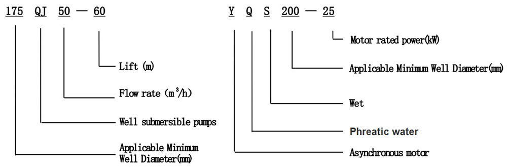
1. model meaning:
2. specifications and performance:
200 QS submersible pump performance table
Non-standard custom series
|
Model |
Model |
|
QS5-70-2.2KW |
QS10-52-4KW |
|
QS5-90-3KW |
QS10-70-5.5KW |
|
QS5-108-4KW |
QS10-90-7.5KW |
|
QS5-126-5.5KW |
QS10-108-7.5KW |
|
QS5-144-5.5KW |
QS20-40-4KW |
|
QS5-160-7.5KW |
QS20-54-5.5KW |
|
QS5-180-7.5KW |
QS20-65-7.5KW |
|
QS10-36-2.2KW |
QS20-81-7.5KW |
|
QS10-54-3KW |
QS32-13-2.2KW |
|
QS10-70-4KW |
QS32-26-4KW |
|
QS10-90-5.5KW |
QS32-52-7.5KW |
|
QS10-108-5.5KW |
QS40-39-7.5KW |
|
QS10-126-7.5KW |
QS40-13-4KW |
|
QS10-140-7.5KW |
QS40-26-5.5KW |
|
QS15-38-3KW |
QS50-13-4KW |
|
QS15-54-4KW |
QS50-26-5.5KW |
|
QS15-65-5.5KW |
QS50-39-7.5KW |
|
QS15-81-5.5KW |
QS63-12-4KW |
|
QS15-100-7.5KW |
QS63-24-7.5KW |
|
QS20-30-3KW |
QS80-11-4KW |
|
QS20-45-4KW |
QS80-22-7.5KW |
|
QS20-60-5.5KW |
QS10-88-7.5KW |
|
QS20-75-7.5KW |
QS10-105-7.5KW |
|
QS20-81-7.5KW |
QS40-52-11KW |
|
QS10-198-15KW |
QS50-60-11KW |
|
QS10-160-9.2KW |
QS65-30-9.2KW |
|
QS15-180-15KW |
QS80-28-9.2KW |
|
QS10-180-11KW |
QS125-15-7.5KW |
Selection of 4. submersible pump
(I) to understand matters of deep well:
For the rational selection and use of submersible pump, need to understand the following contents.
1. The requirements in the conditions of use.
2. Inner diameter and depth of deep well pipe.
3. Static water level and dynamic water level of deep well.
4, the best water inflow of deep wells.
The base number of the (II) submersible pump (suitable for the minimum well diameter) should be less than or equal to the inner diameter of the deep well.
(III) submersible pump flow should be appropriate, can not exceed the optimal water inflow, otherwise it will cause the movement of sand in the aquifer, causing sand in the well, resulting in damage to the submersible pump.
(4) The head required for submersible pumps can be calculated according to the following formula.
H 需=H1 H2 H3
In the formula: H requires: the lift required by the submersible pump.
H1: Vertical distance from the dynamic water level in the well to the water outlet.
H2: Loss along the pump pipe inside and outside the well (see the table below).
H3: kinetic head at the outlet (generally less than 0.5 meters can be ignored).
When selecting a water pump, the required lift H must be the basis for selecting the rated lift H of the submersible electric pump. Generally, the rated lift of the selected water pump
The stroke should be greater than or equal to the required head and closest to the required head specification.
|
Flow → Well pipe ↓ |
5 |
8 |
10 |
15 |
20 |
25 |
32 |
40 |
50 |
63 |
80 |
100 |
125 |
140 |
200 |
|
50 |
1.5 |
3.9 |
6.1 |
13.8 |
24.5 |
||||||||||
|
65 |
1.5 |
3.5 |
6.2 |
9.6 |
15.8 |
24.6 |
|||||||||
|
80 |
2.0 |
3.2 |
5.2 |
8.1 |
12.7 |
20.1 |
|||||||||
|
100 |
1.6 |
2.6 |
4.0 |
6.3 |
10.2 |
16.0 |
24.9 |
||||||||
|
125 |
2.0 |
3.2 |
5.0 |
7.8 |
9.2 |
20.1 |
|||||||||
|
150 |
2.0 |
3.2 |
4.0 |
8.1 |
Note: 1. The unit of flow is ton/hour, and the unit of well pipe is millimeter.
2. The value in the table is the loss along the way (m) of 100 m steel pipe. If plastic pipe is used, the loss along the way is about 0.7 times of that of steel pipe.
Introduction to 5. Structure
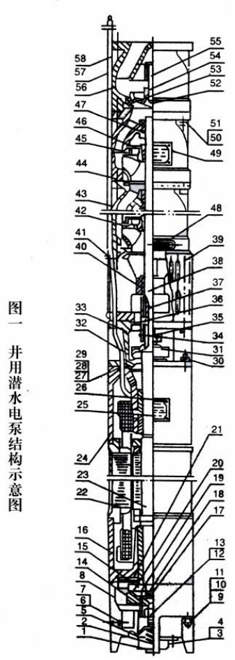
The (I) structure is shown in Figure 1:
The water pump part is mainly composed of water pump shaft, impeller, guide shell, rubber bearing, check valve body (optional) and other parts. The motor part mainly includes base, pressure regulating film, thrust bearing, thrust plate, lower guide bearing seat, stator, rotor, upper guide bearing seat, sand throwing ring and water inlet.
Section, lead-out cable and other parts.
(ii) Main features:
1. The motor is a water-filled wet submersible three-phase asynchronous motor. The motor cavity is filled with clean water to cool the motor and lubricate the bearings. The pressure regulating film at the bottom of the motor is used to adjust the expansion and contraction pressure difference of the water inside the body caused by the temperature rise of the motor.
2. In order to prevent the sand in the well water from entering the inside of the motor, two oil seals are installed at the upper shaft extension of the motor, and a sand ring is installed to form a sand control structure.
3. In order to prevent the water pump shaft from moving up when starting, the water pump shaft and the motor shaft are connected as a whole by a coupling, and an upper thrust bearing is installed at the lower part of the motor.
4. The lubrication of motor and water pump bearing is water lubrication.
5. The motor stator winding adopts high-quality submersible motor winding wire with high insulation performance.
6. The pump adopts computer CAD design, simple structure and good technical performance.
VI. Installation
Preparation before (I) installation:
1. Check whether the submersible pump meets the conditions and scope of use specified in the manual.
2, with a diameter equal to the maximum outer diameter of the submersible pump weight, measure whether the inner diameter of the well hole can be put into the submersible pump, and measure whether the well depth meets the installation requirements.
3. Check whether the well hole is cleaned and whether the well water is turbid. Never use submersible pump to clean the well or pump mud and sand water to avoid premature damage to the submersible pump.
4. Check whether the position of the wellhead installation clamp is appropriate and whether it can withstand the quality of the entire unit.
5. Check whether the submersible pump parts are complete and installed well according to the assembly drawing of the instruction manual. Remove the filter screen and rotate the coupling to see if the rotation is flexible.
6. Unscrew the water filling bolt, fill the motor cavity with non-corrosive clean water (note: be sure to fill it up), and then screw on the water filling bolt. After 12 hours of water injection, the insulation resistance of the motor measured with a 500V shaking table shall not be less than 150MΩ.
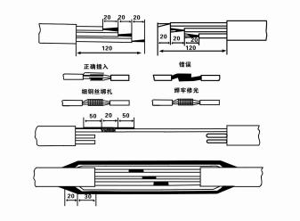
7, cable joint, will lead out the cable and cable with one end with an electricist knife to cut 120mm rubber sleeve, and then the three strands of core wire length step staggered, stripping out 20mm copper core, with a knife scraping or emery cloth sand to remove the outer oxide layer of copper wire, will butt the two wire ends inserted, with fine copper wire wrapping layer tied tightly, with soldering, welding, welding, surface sand to scratch. Then the three joints are respectively wrapped with polyester insulating tape in half-stack, the two ends of the wrapping layer are tightly wrapped with nylon thread, then the tape is wrapped in half-stack method in 3 layers, the outside is wrapped with high-voltage insulating tape in 3 layers, finally the 3 strands are folded, and the high-voltage adhesive tape is repeatedly wrapped in 5 layers. Each layer of wrapping must be tightened, and the joints between the layers must be tight and firm to prevent water from damaging the insulation. After bandaging, soak in room temperature water at 20 ℃ for 12 hours, and measure the insulation resistance with a shaking table, which shall not be less than 100MΩ.
Attached cable wiring process drawings are as follows:
|
58 |
Lead out cable |
Foot |
|
57 |
Line guard |
|
|
56 |
check valve body |
1 |
|
55 |
Valve body |
1 |
|
54 |
Rubber pad |
1 |
|
53 |
Cushioning rubber pad |
1 |
|
52 |
valve disc |
1 |
|
51 |
Spring pad 12 |
Foot |
|
50 |
Bolt M12 × 30 |
Foot |
|
49 |
Nameplate of water pump |
1 |
|
48 |
Steering Placard |
1 |
|
47 |
Rubber bearing |
|
|
46 |
taper sleeve |
|
|
45 |
Upper Seal Ring |
|
|
44 |
Lower seal ring |
|
|
43 |
guide shell |
|
|
42 |
Impeller |
|
|
41 |
Screw |
4 |
|
40 |
Water inlet section |
1 |
|
39 |
Filter |
1 |
|
38 |
Water pump shaft |
1 |
|
37 |
Key C8 × 30 |
2 |
|
36 |
Coupling |
1 |
|
35 |
cylindrical screw |
2 |
|
34 |
Lock ring |
1 |
|
33 |
Join Segment |
1 |
|
32 |
Oil seal |
3 |
|
31 |
Sand-throwing ring |
1 |
|
30 |
Tie rod screw |
1 |
|
29 |
Cable pressure ring |
1 |
|
28 |
Cable packing |
1 |
|
27 |
Cable rubber pad |
1 |
|
26 |
Nameplate rivet |
8 |
|
25 |
Motor Nameplate |
1 |
|
24 |
Upper guide bearing seat |
1 |
|
23 |
Rotor |
1 |
|
22 |
Stator |
1 |
|
21 |
Upper thrust bearing |
1 |
|
20 |
Thruster disc |
1 |
|
19 |
Thrust bearing seat |
1 |
|
18 |
Key C8 × 25 |
1 |
|
17 |
Left-hand nut |
1 |
|
16 |
Lower guide bearing seat |
1 |
|
15 |
Thrust seat |
1 |
|
14 |
Thrust bearing |
1 |
|
13 |
Adjusting bolt |
1 |
|
12 |
Nut |
1 |
|
11 |
Tie rod screw |
8 |
|
10 |
Spring pad 12 |
8 |
|
9 |
Nut M12 |
8 |
|
8 |
Base |
1 |
|
7 |
Rubber pad |
1 |
|
6 |
Water drain screw |
1 |
|
5 |
Pressure regulating membrane |
1 |
|
4 |
Spring pad 6 |
4 |
|
3 |
Bolt M16 × 16 |
4 |
|
2 |
Pressure regulating spring |
1 |
|
1 |
Bottom cover |
1 |
|
Serial Number |
Name |
Quantity |
8. Use a multimeter to check whether the three-phase wires are conductive and whether the DC resistance is approximately balanced.
9. Check whether the capacity of the circuit and transformer is overloaded, and then connect the overload protection switch or starting equipment. See Table 2 for the specific model. Then fill a bucket of water into the water pump from the water outlet of the water pump to lubricate the rubber bearing in the pump. Then the submersible electric pump will be put upright and stable, and start instantaneously (not more than one second) to see if the steering is consistent with the steering sign, if the opposite, the three-phase cable can be replaced with any two joints, and then the filter screen is installed to prepare for going into the well. If it is used in special occasions (such as in ditches, canals, rivers, ponds, pools, etc.), the electric pump must be reliably grounded.
(II) installation equipment and tools:
1, more than two tons of chain one pay.
2. A tripod with a vertical height of not less than four meters.
3. Two ropes (wire ropes) that can bear more than one ton of weight (can bear the weight of a full set of pumps).
4. Install two sets of clamps (splints).
5. Wrenches, hand hammers, screwdrivers, electrical tools and instruments, etc.
(III) electric pump installation:
1. See Figure 2 for the installation drawing of submersible electric pump, and see Table 3 for the installation dimensions of submersible electric pump.
2. Submersible electric pumps with a lift of less than 30 meters can be hoisted in the well directly with wire ropes or other hemp ropes that can bear the full weight of the whole machine, water pipes and water in the pipes.
3. The pump with a head of more than 30 meters adopts steel pipe, and the installation sequence is as follows:
① Clamp the upper end of the water pump with a clamp (the motor has been connected with the water pump at this time) and lift it with a lifting chain, slowly tie it into the well until the clamp is put on the wellhead, and remove the lifting chain.
② Clamp a pipe with another clamp, lift it with a chain 15cm away from the flange, and put it down slowly. The pipe flange and the pump flange are in the middle of the rubber pad, and the pipe and the pump are tightened evenly with bolts, nuts and spring pads.
③ Slightly lift the submersible pump, remove the clamp at the upper end of the pump, tie the cable on the water pipe with a plastic band, and tie it down slowly so that the clamp is placed on the wellhead.
④ Use the same method to tie all water pipes into the well.
⑤ After the lead-out cable is connected to the control switch, it is connected to the three-phase power supply.
Precautions during (IV) installation:
1. If stuck phenomenon is found in the process of pumping down, the water delivery pipe should be rotated or pulled to overcome the stuck point. If various measures are still ineffective, do not force down the pump to avoid jamming and damage to the submersible pump and the well.
2. During installation, rubber pads shall be placed at the flange of each pipe and tightened evenly.
3. When the water pump goes down the well, it should be placed in the middle of the well pipe to prevent the pump from vibrating due to the long-term operation of the water pump against the well wall, the motor sweeping and burning.
4, according to the flow of sand, silt well, determine the pump to the bottom of the depth, must not be the pump buried in the silt, pump to the bottom of the distance is generally not less than 3 meters (see Figure 2).
5. The water inlet depth of the water pump should be no less than 1- 1.5 meters from the water inlet (see Figure 2), otherwise, the water pump bearing will be easily damaged.
6. The use head of the water pump cannot be too low. Otherwise, it is necessary to install a gate valve on the wellhead water pipeline to control the flow of the water pump at the rated flow point to prevent the motor from being overloaded and burned due to large flow.
7. During the operation of the water pump, the water output should be continuous and uniform, and the current should be stable (under rated conditions, generally not exceeding 10% of the rated current), without vibration and noise. If there is any abnormality, stop the machine to find out the reason and eliminate it.
8. Pay attention to the setting of the grounding wire of the motor during installation (see Figure 2). When the water delivery pipe is a steel pipe, the lead wire shall be drawn from the wellhead clamp; When the water delivery pipe is a plastic pipe, the lead wire shall be drawn from the grounding mark of the electric pump.
7. submersible pump matching switch, cable table
Table II
|
Motor power K W → Project ↓ |
2.2-4 |
5.5 |
7.5 |
9.2 |
11 |
13 |
15 |
18.5 |
22 |
|
Supporting switch |
QZ610-4 |
0Z610-10 |
OZ610-17 |
XJ01-20 |
XJ01-22 |
||||
|
Supporting cable |
1.5mm ² |
2.5 mm² |
4 mm² |
4 mm² |
4 mm² |
6 mm² |
6 mm² |
10 mm² |
10 mm² |
|
Motor power K W → Project ↓ |
25 |
30 |
37 |
45 |
55 |
63 |
75 |
90 |
100 |
|
Supporting switch |
XJ01-30 |
XJ01-40 |
XJ01-40 |
XJ01-55 |
XJ01-55 |
XJ01-75 |
XJ01-75 |
XJ01-100 |
XJ01-100 |
|
Supporting cable |
10 mm² |
16 mm² |
16 mm² |
25 mm² |
25 mm² |
35 mm² |
35 mm² |
50 mm² |
50 mm² |
Note: 1. The cable length is rated lift of submersible pump plus 2 meters.
2. The cable matching standards listed in this table are for reference only, and the selection shall be increased or decreased according to the change of lift.
List of installation dimensions of submersible pump
Table III
|
Installation size model |
Outlet diameter |
Connection dimension of upper guide housing |
Connection dimension of check valve body |
Size of pump seat |
||||||||
|
Stop |
Center distance |
Outer diameter |
N-φd |
Stop |
Center distance |
Outer diameter |
N-φd |
Length |
Width |
Center distance |
||
|
150QJ5 |
40 |
90 |
110 |
133 |
4-φ11 |
80 |
98 |
133 |
4-φ11 |
280 |
230 |
110 |
|
150QJ10/20 |
50 |
85/90 |
110 |
125/127 |
4-φ11 |
110 |
130 |
4-φ11 |
280 |
230 |
110 |
|
|
150QJ32 |
80 |
95 |
110 |
130 |
4-φ11 |
110 |
130 |
4-φ11 |
280 |
230 |
110 |
|
|
150QJ63 |
80 |
110 |
125 |
141 |
4-φ11 |
110 |
125 |
141 |
4-φ11 |
350 |
250 |
125 |
|
175QJ101520 |
50 |
110 |
132 |
158 |
4-φ12 |
110 |
132 |
160 |
4-φ13 |
350 |
250 |
125 |
|
175QJ25 |
65 |
110 |
132 |
158 |
4-φ12 |
110 |
132 |
160 |
4-φ13 |
350 |
250 |
132 |
|
175QJ324050 |
80 |
110 |
132 |
162 |
4-φ12 |
110 |
132 |
160 |
4-φ13 |
350 |
250 |
132 |
|
175QJ6380 |
80 |
110 |
132 |
160 |
4-φ12 |
120 |
145 |
162 |
4-φ13 |
350 |
250 |
132 |
|
200QJ2025 |
50 |
110 |
145 |
170 |
4-φ13 |
145 |
170 |
4- 13 |
350 |
250 |
125 |
|
|
200QJ324050 |
80 |
125 |
145 |
170 |
8-φ13 |
145 |
170 |
8-φ13 |
350 |
250 |
145 |
|
|
200QJ63/80 |
80/100 |
125 |
145 |
174 |
3-φ13 |
145 |
174 |
B-φ13 |
350 |
250 |
145 |
|
|
200QT100 |
100 |
125 |
145 |
180 |
8-φ13 |
145 |
174 |
8-φ13 |
350 |
250 |
145 |
|
|
250QJ405063 |
80 |
120 |
140 |
180 |
8-φ13 |
120 |
140 |
170 |
8-φ13 |
350 |
250 |
140 |
|
250QJ80100125 |
100 |
140 |
160 |
190 |
8-φ13 |
140 |
160 |
190 |
B-φ13 |
500 |
350 |
160 |
|
250QJ140 |
125 |
140 |
185 |
215 |
3-φ13 |
140 |
190 |
215 |
8-φ13 |
500 |
350 |
190 |
|
250QJ200 |
150 |
160 |
195 |
220 |
8-φ13 |
140 |
190 |
215 |
8-φ13 |
500 |
350 |
190 |
|
300QJ125140 |
125 |
140 |
160 |
190 |
3-φ13 |
140 |
190 |
215 |
B-φ13 |
500 |
350 |
190 |
|
300QJ200 |
150 |
165 |
210 |
240 |
8-φ13 |
192 |
210 |
240 |
8-φ13 |
500 |
350 |
190 |
|
300QJ320 |
200 |
195 |
225 |
260 |
8-φ13 |
204 |
225 |
250 |
8-φ13 |
630 |
450 |
225 |
|
400QI500 |
250 |
280 |
315 |
345 |
8-φ18 |
315 |
340 |
8-φ18 |
630 |
450 |
315 |
|
7. Maintenance and Maintenance
1. After the submersible pump is installed, check the insulation resistance and three-phase conduction from the switch again, check whether there is any error in the connection of the instrument and the starting equipment, if there is no problem, start the test machine, and observe whether the indicated reading of each instrument exceeds the rated power specified in the nameplate after starting.
Pressure and current, observe whether the pump noise and vibration phenomenon, all normal can be put into operation.
2. After the pump runs for the first time for four hours, it should be stopped to quickly test the thermal insulation resistance of the motor, and its value should not be less than 0.5 megohms.
3. After the pump is stopped, it should be started after an interval of five minutes to prevent the water column in the pipe from flowing back completely and causing the motor to burn out due to excessive current.
4. After the pump is put into normal operation, in order to extend its service life, it is necessary to regularly check whether the power supply voltage, working current and insulation resistance are normal. If the following conditions are found, it should be stopped immediately to eliminate the fault.
① Under rated conditions, the current exceeds 20%.
② The dynamic water level drops to the inlet section, causing intermittent water discharge.
The submersible pump vibration or noise.
The power supply voltage is less than 340 volts.
⑤ One phase of fuse is burnt out.
The water pipe is damaged.
⑦ The insulation resistance of the motor to ground is lower than 0.5 megohm.
5. Unit disassembly:
① Untie the cable tether, remove the pipeline part, and remove the wire guard plate.
② Unscrew the drain bolt to drain the water in the motor cavity.
③ Remove the filter screen and loosen the fixing screw of the motor shaft on the coupling.
④ Unscrew the bolt connected with the motor at the water inlet joint, and separate the water pump from the motor (pay attention to flat the unit during separation to prevent the pump shaft from bending)
⑤ The disassembly sequence of the water pump is: (see Figure 1) Inlet joint, impeller, guide shell, impeller... Check the valve body, and use special workers when disassembling the impeller.
First loosen the tapered sleeve that fixes the impeller, and avoid bending the pump shaft and bruising all parts during disassembly.
⑥ The motor disassembly process is as follows: (see Figure 1) Place the motor on the platform, and sequentially remove the nut, base, shaft head lock nut, thrust plate, key, and lower guide from the bottom of the motor. Bearing seat, stud, and then take out the rotor (be careful not
Damage to the wire package) Finally, remove the coupling section and the upper guide bearing seat.
⑦ Unit assembly:
Before assembly, the rust and dirt of each component shall be cleaned, the mating surfaces and fasteners shall be coated with sealant, and then assembled in the reverse order of disassembly (the up and down movement of the motor shaft after assembly is about 1mm). After assembly, the coupling shall be moved flexibly, and then the filter screen shall be installed for testing.
6. If the submersible pump has been in operation for one year, or if it has been in operation for less than one year but the diving time has reached two years, the well shall be disassembled and overhauled according to Article 5 and the worn parts shall be replaced.
8. fault causes and troubleshooting
Table IV
|
Fault phenomenon |
Cause |
Exclusion method |
|
No water or intermittent Outlet or less water |
1. The motor does not start (if the voltage is low, the wire is too thin and too long, the voltage drop is too large or the pump is stuck and cannot start) 2. The pipeline is blocked or the water filter is blocked 3. Pipeline rupture 4. The suction port is exposed to the water surface 5. The submersible pump turns to the opposite 6. Wear of impeller mouth ring and sealing ring |
1. Eliminate circuit faults, find out the cause of sticking and eliminate it 2. Remove blockage 3. Repair the rupture 4. Lower the submersible pump. If there is still no water, it may exceed the lift range of the submersible pump. It is recommended to change the pump. 5. Replace any two connectors of the cable 6. Replace the new impeller and seal ring |
|
Excessive current or electricity Flow table pointer wobble |
1, large flow, low lift beyond the scope of use, motor overload 2. The graphite bearing of the motor is worn, and the rubber bearing or shaft sleeve of the water pump is worn. 3. Wear of thrust bearing and lower seat of impeller 4. The pump shaft is bent and the bearing is not concentric |
1. Reduce the flow 2. Replace the new bearing or shaft sleeve 3. Replace the thrust bearing and thrust plate 4. The shaft bending shall be sent to the factory for overhaul, and the new bearing shall be replaced. |
|
Insulation resistance of motor winding to ground thermal state Less than 0.5 megohms |
1. Aging or breakage of electromagnetic wire insulation 2. Damaged rubber cable 3. Sealing joint failure |
1. Disassemble the winding, wrap the damaged part with adhesive tape or rewind the new coil 2. Find out the damage and wrap it with adhesive tape or repair it with fire. 3. Disassemble, connect and re-bandage |
|
The motor does not start and there is a buzzing sound. |
1. Conductor phase disconnection or switch disconnection (single-phase operation) 2. Motor guide bearing holding shaft 3. There is foreign matter in the impeller and the pump body is stuck 4, the voltage is too low |
1. Repair the broken wire and connect the fuse 2. Repair or replace bearings and shaft repair 3. Remove foreign matters 4. Adjust the voltage |
|
Severe vibration of motor |
1. Unbalance of motor rotor 2. Imbalance of impeller 3. Pump shaft bending 4. Wear of bearing (shaft sleeve) |
1. Dynamic balancing of rotor 2. Static balance of impeller 3. Straightening pump shaft 4. Replace bearing and shaft sleeve |
|
Motor winding burned |
1. Water shortage in motor 2. Single-phase operation 3. Long time overload operation |
1, pay attention to must be filled with water 2. Check and adjust the starting protection equipment to ensure the normal operation of the motor 3. Reduce the load so that the current and voltage cannot exceed the rated value on the nameplate |
Storage and safekeeping of 9. unit
1. Drain all the water in the motor cavity (especially in winter to prevent freezing damage to the motor), and tie up the cable reel.
2. Store in a room with no corrosive substances and gases and a temperature below 40 ℃.
3, long-term use should pay attention to the submersible pump rust.
X. Scope of Complete Belt
1. Submersible pump.
2. Submersible motor. (The volume and weight are small before leaving the factory and the submersible pump have been assembled as a whole).
3, cable, adhesive tape (according to the contract can not be taken).
4, water pipe, elbow, tape, bolt, spring pad, clamp (splint) two (according to the contract without).
5. One certificate (and warranty card).
6. A copy of the instructions.
XI. Vulnerable Parts
1. Impeller
2. Shaft sleeve
3. Rubber shaft sleeve
4. Seal ring
Previous:
The next one:
Online consultation


About Us
Hebei Quanyou Pump Industry Co., Ltd. is a( high-tech enterprise integrating research and development December 1, 2021-December 1, 2024), production, sales and service of water pumps. Its main products are QJ series submersible pumps for wells, QJ series stainless steel submersible pumps, and QS series submersible pumps.
Contact Us
Telephone:86-319-7132979
Mobile:86-13932918197
Mailbox:hbqy18197@163.com yuer@wellpumpqy.com
WhatsApp:86-17855846635(Sissie)
Address: Lincheng County, Xingtai City, Hebei Province, China
